
- #ARDUINO PWM PIN 11 VARSPEEDSERVO SERIAL#
- #ARDUINO PWM PIN 11 VARSPEEDSERVO DRIVERS#
- #ARDUINO PWM PIN 11 VARSPEEDSERVO DRIVER#
- #ARDUINO PWM PIN 11 VARSPEEDSERVO FULL#
- #ARDUINO PWM PIN 11 VARSPEEDSERVO SOFTWARE#

#ARDUINO PWM PIN 11 VARSPEEDSERVO SOFTWARE#
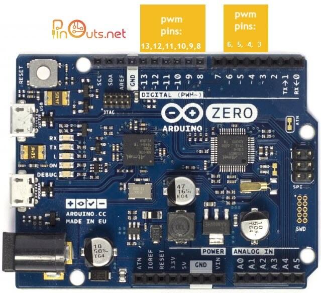
Unlike the PWM pins, DAC0 and DAC1 are Digital to Analog converters, and act as true analog outputs.' You could do software pwm but the frequency will be several orders of magnitude less than the clock frequency.
#ARDUINO PWM PIN 11 VARSPEEDSERVO SERIAL#
Myservo.Hopefully this isn't too basic of a question but I'm having trouble getting the serial to write the degrees of two servos using VarSpeedServo - I'm mapping color values from a sensor into a processing sketch, and need to be able to map their locations by tracking the x and y servo degrees. 'The Arduino Due supports analogWrite () on pins 2 through 13, plus pins DAC0 and DAC1. Int pos = 0 // variable to store the servo position twelve servo objects can be created on most boards Servo myservo // create servo object to control a servo This maybe caused by noise on the PWM signal. It worked but the servo was rather shaky after reaching its final position. I also controlled the servo with serial command. Two of servos I tried to move were broken which also cost me some time to figure out. I used a demo code from the Arduino examples. Otherwise, you will waste hours of trying to figure out what is wrong with the code or the serial library or your Arduino board. If you are using the serial monitor to control the speed of the motor, make sure to select No line ending in the dropdown menu. I used the following code to control the motor, applying serial commands to control the speed. I will probably do so in my final design but in this case, I will power the Arduino from USB, the ESC for the BLDC motor will get its power from the external supply at 12 V. ESC containing BECs can also be used to power components with lower voltage (basically containing step down elements), which is the common way for 5 V receivers of a radio controlled plane or drones. For testing, I'm using an 20 A ESC with no BEC (battery eliminator circuit). The electronic speed controller (ESC) needs the GND level as well as a PWM signal generated by the microcontroller. As building my own power electronics however is rather complex, I will rely on "off the shelf" components from a commercial vendor. For a BLDC motor, there wiring is rather easy. My next output device is the brushless DC (BLDC) motor. I set the wait variable to 500 which worked fine. If it is not set correctly, the motor will only buzz but not move a step. However, it took some tweaking of the waiting time. The motor is working with the sample code which runs on the Arduino. The final design will run on a 3S lipo battery which will me 11.1 V. In my case, I selected a motor voltage VMOT of 12 V which comes from an external power supply. Coil 1 and 2 need to be connected accordingly. On the right hand side (left image), you can see the wiring for the motor.
#ARDUINO PWM PIN 11 VARSPEEDSERVO FULL#
As I won't need high precision, I will go with full step size, connecting all pins to GND level.

The three pins marked MS control the step size. 11 void emotionalmove (EmotionalServo &servo, int ( fref)(), int ( fstop).
#ARDUINO PWM PIN 11 VARSPEEDSERVO DRIVER#
The stepper motor driver needs a level of 5 V for basically three signals, which are ENABLE, STEP and DIR. the analog input of the pin pin stop is equal to a constant value value, or. I connected my Arduino, the motor driver and the motor on a breadboard. I will use a commercial Pololu stepper motor driver which I found here.
#ARDUINO PWM PIN 11 VARSPEEDSERVO DRIVERS#
These stepper motor drivers can either be build or bought. Stepper motor need additional hardware to be operated. My first output device will be a stepper motor.

I will go trough it one by one, before starting to design the actual Satshakit modifcation. This will contain, two servos, a stepper motor and two BLDC motors. I will test all of the output devices of my final project upfront in an Arduino setup.


 0 kommentar(er)
